Page:EB1911 - Volume 27.djvu/421
tunnel walls were then built in the chamber. For the remaining part of the river the foregoing process was varied by cutting off the sheet piling at mid-height of the tunnel and making the upper half of the tunnel, which was built above and lowered in sections through the water, serve as the roof of the chamber in which the lower half of the tunnel was built.
| Tunnel. | Location. | Length. (miles) |
Internal Width and Height. |
Material penetrated |
Average progress per day = 24 hrs. (lin. yds.). |
Approximate cost per lin. yd. |
| Mont Cenis (1 tunnel) | Modane, France and Bardonecchia, Italy. |
7·98 | 26 ft. 3 in. ✕ 24 ft. 7 in. (horseshoe). |
Granitic |
2·57 |
£ 226 |
| St Gotthard (1 tunnel) | Göschenen and Airolo in Switzerland. |
9·3 | 26 ft. 3 in. ✕ 24 ft. 7 in. (horseshoe). |
Granitic | 6·01 | 143 |
| Arlberg (1 tunnel) | Innsbruck and Bludenz in Tirol |
6·36 | 25 ft. 3 in. wide. | — | 9·07 | 108 |
| Simplon (2 tunnels) | Brigue, Switzerland and Iselle, Italy. |
12·3 | 16 ft. 5 in. ✕ 19 ft. 6 in. each (min.). |
Gneiss, mica schist, limestone and disintegrated mica schist rock. |
11·63 | 148 |
The tunnels of the Métropolitain railway of Paris (F. Bienvenüe, engineer-in-chief) under the two arms of the Seine, between Place Chatelêt and Place Saint Michel, were made by means of compressed-air caissons sunk beneath the river bed, L. Chagnaud being the contractor. They were built of plates of sheet steel and masonry, with temporary steel diaphragms in the ends, filled with concrete, making a cross wall with a level top about even with the outside top of the tunnel and about 2 ft. below the bottom of the Seine. The caissons were sunk on the line of the tunnel so that adjacent ends (and the walls just described) were nearly 5 ft. apart with—at that stage—a core of earth between them. Side walls joining the end walls and thus enclosing the earth core on four sides (fig. 4) were next made by the aid of temporary small caissons sunk through about 26 ft. of earth under the river.
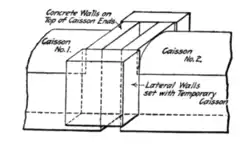 |
| (From Engineering News, New York.) |
| Fig. 4.—Perspective showing manner of enclosing space between tunnel caissons for the Métropolitain under the Seine at Paris. |
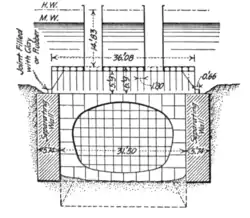
The tops of the side walls were made even with the end walls. A steel rectangular coffer-dam (figs. 5 and 6) was sunk to rest with rubber or clay joint on these surrounding walls. The coffer-dam had shafts reaching above the surface of the water, so that the earth core was easily taken out (after removing the water) in free air. The adjacent chambers under the caissons were then connected together. Three caissons, of a total length of 396 ft., were used under the larger arm, and two, of an aggregate length of 132 ft., under the smaller arm of the Seine. The cost of the tunnel was 7000 francs per lineal metre.
 |
 |
| (From Engineering News, New York.) | |
| Fig. 5.—Transverse Section. | Fig. 6.—Longitudinal Section. |
| Coffer-dam superimposed over joints between caissons in tunnels for the Métropolitain under the Seine at Paris. | |
William Sooy Smith published in Chicago, in 1877, a description of a scheme for building a tunnel under the Detroit river by sinking caissons end to end, each caisson to be secured to the adjoining one by tongued and grooved guides, and a nearly water-tight connexion between the two to be made by means of an annular inflated hose.
Tunnelling through Mountains.—Where a great thickness of rock overlies a tunnel through a mountain, it may be necessary to do the work wholly from the two ends without intermediate shafts. The problem largely resolves itself into devising the most expeditious way of excavating and removing the rock. Experience has led to great advances in speed and economy, as may be seen from examples in the above table.
In 1857 the first blast was fired in connexion with the Mont Cenis works; in 1861 machine drilling was introduced; and in 1871 the tunnel was opened for traffic. With the exception of about 300 yds. the tunnel is lined throughout with brick or stone. During the first four years of hand labour the average progress was not more than 9 in. per day on each side of the Alps; but with compressed air rock-drills the rate towards the end was five times greater.
In 1872 the St Gotthard tunnel was begun, and in 1881 the first locomotive ran through it. Mechanical drills were used from the beginning. Tunnelling was carried on by driving in advance a top heading about 8 ft. square, then enlarging this sideways, and finally sinking the excavation to invert level (see figs. 7 and 8). Air for working the rock-drills was compressed to seven atmospheres by turbines of about 2000 horse-power.
The driving of the Arlberg tunnel was begun in 1880 and the work was completed in little more than three years. The main heading was driven along the bottom of the