Page:EB1911 - Volume 27.djvu/41
(fig. 39) or a circular rack with Pinions (fig. 40), turned with a key which operates all the jaws simultaneously inwards or outwards. But as some classes of jobs have to be adjusted eccentrically, many chucks are of the combination type (fig. 40), capable of being used independently or concentrically, hence termed universal chucks. The change from one to the other simply means throwing the ring of teeth out of or into engagement with the pinions by means of cams or equivalent devices. Each type of chuck occurs in a large range of dimensions to suit lathes of all centres, besides which every lathe includes several chucks, large and small, in its equipment. The range of diameters which can be taken by any one chuck is limited, though the jaws are made with steps, in addition to the range afforded by the operating screws. The "Taylor" spiral chucks (fig. 41) differ essentially from the scroll types in having the actuating threads set spirally on the sloping interior of a cone. The result is that the outward pressure of each jaw is received behind the body, because the spiral rises up at the back. In the ordinary scroll chucks the pressure is taken only at the bottom of each jaw, and the tendency to tilt and pull the teeth out of shape is very noticeable. The spiral, moreover, enables a stronger form of tooth to be used, together with a finer pitch of threads, so that the wearing area can be increased.
The foregoing may be termed the standard chucks. But in addition there are large numbers for dealing with special classes of work. Brass finishers have several. Most of the hollow spindle lathes and automatics have draw-in or push-out chucks, in which the jaws are operated simultaneously by the conical bore of the encircling nose, so that their action is instantaneous and self-centring. They are either operated by hand, as in fig. 31, or automatically, as in fig. 33. There is also a large group used for drills and reamers—the drill chucks employed in lathes as well as in drilling machines.
II.—Reciprocating Machine Tools
This is the only convenient head under which to group three great classes of machine tools which possess the feature of reciprocation in common. It includes the planing, shaping and slotting machines. The feature of reciprocation is that the cutting tool is operative only in one direction; that is, it cuts during one stroke or movement and is idle during the return stroke. It is, therefore, in precisely the same condition as a hand tool such as a chisel, a carpenter's plane or a hand saw. We shall return again to this feature of an idle stroke and discuss the devices that exist to avoid it.
Planing Machines.—In the standard planer for general shop purposes (fig. 42) the piece of work to be operated on is attached to a horizontally table moving to and fro on a rigid bed, and passing underneath the fixed cutting tool. The tool is gripped in a box having certain necessary adjustments and movements, so that the tool can be carried or fed transversely across the work, or at right angles with the direction of its travel, to take successive cuts, and also downwards or in a vertical direction. The tool-box is carried on a cross-slide which has capacity for several feet of vertical adjustment on upright members to suit work of varying depths. These uprights or housings are bolted to the sides of the bed, and the whole framing is so rigidly designed that no perceptible tremor or yielding takes place under the heaviest duty imposed by the stress of cutting.
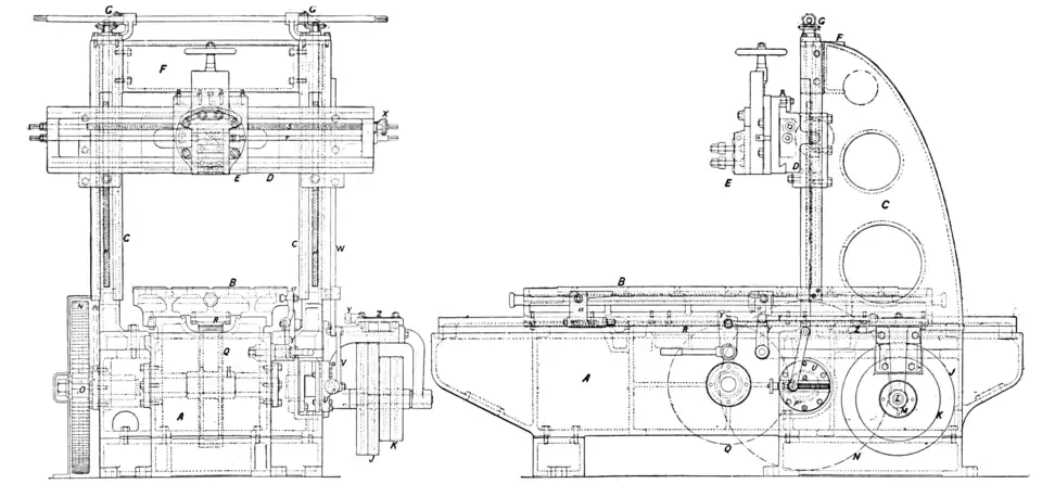
Fig. 42.—Planing Machine to take work 5 ft. in length X 2 ft. 6 in. wide X 2 ft. 6 in. in height. (Greenwood & Batley, Ltd., Leeds.)
A, Bed.
B, Table.
C, C, Housings.
D, Cross-rail.
E, Tool-box.
F, Stretcher.
G, G, Bevel-gears for elevating cross-slide by means of screw H, H.
J, Fast and loose pulleys for driving the table during the cutting stroke.
K, Pulleys for non-cutting stroke.
L, Pulley shaft.
M, Pinion on ditto, driving wheel N.
O, Shaft of N carrying pinion P, which drives Q, engaging with the rack R on the underside of the table B.
S, Traverse screw actuating linear movement of tool-box, E.
T, Splined rod for actuating down-feed of tool-box.
U, Slotted feed disk rotated by shaft O.
V, Lever adjustable across disk.
W, Toothed rack reciprocated vertically by disk and lever, and operating feed gear-wheels on shafts S and T.
X, Ratchet feed.
a, a, Dogs adjustable in slot at the edge of the table B.
Y, Y, Levers actuated by dogs, and operating belt-shifting forks Z.