Page:EB1911 - Volume 27.djvu/33
changes are rung in great variety, ranging from the Qarrow slitting tools which saw off bars, to the broad cutters of 24 in. or more in width, used on plano-millers.
When more than about an inch in width, surfacing cylindrical cutters are formed with spiral teeth (fig. 15, B), a device which is

Fig. 17.
A, Straddle Mill, cutting faces and edges.
B, Set of three mills cutting grooves.

Fig. 18.—Group of Angular Mills.
A, Cutter with single slope.
B, Ditto, producing teeth in another cutter.
C, Double Slope Mill, with unequal angles.
essential to sweetness of operation, the action being that of shearing. These have their teeth cut on universal machines, using the dividing and spiral head and suitable change wheels, and after hardening they are sharpened on universal grinders. When cutters exceed about 6 in. in length the difficulties of hardening and grinding render the "gang" arrangement more suitable. Thus, two, three or more similar edge mills are set end to end on an arbor, with the spiral teeth running in reverse directions, giving a broad face with balanced endlong cutting forces. From these are built up the numerous gang mills, comprising plane faces at right angles with each other, of which the straddle mills are the best known (fig. 17, A). A common element in these combinations is the key seat type B having teeth on the periphery and on both faces as in fig. 15, C, D. By these combinations half a dozen faces or more can be tooled simultaneously, and all alike, as long as the mills retain their edge. The advantages over the work of the planer in this class of work are seen in tooling the faces and edges of machine tables, beds and slides, in shaping the faces and edges of caps to fit their bearing blocks. In a single cutter of the face type, but having teeth on back and edge also, T~slots are readily milled (fig. 16, D); this if done on the planer would require re-settings of awkwardly cranked tools, and more measurement and testing with templets than is required on a milling machine.
When angles, curves and profile sections are introduced, the capacity of the milling cutter is infinitely increased. The making of the cutters is also more difficult. Angular cutters (fig. 18) are used for producing the teeth of the mills themselves, for shaping the teeth of ratchet wheels, and, in combination with straight cutters in gangs, for angular sections. With curves, or angles and curves in combination, taps, reamers and drills can be fluted or grooved, the teeth of wheels shaped, and in fact any outlines imparted (fig. 19). Here the work of the fitter, as well as that of the planing and allied machines, is invaded, for much of this work if prepared on these machines would have to be finished laboriously by the file.
There are two ways in which milling cutters are used, by which

Fig. 19.
A, Convex Cutter.
B, Concave Cutter.
C, Profile Cutter.
their value is extended; one is to transfer some of their work proper to the lathe and boring machine, the other is by duplication. A good many light circular sections, as wheel rims, hitherto done in lathes, are regularly prepared in the milling machine, gang mills being used for tooling the periphery and edges at once, and the wheel blank being rotated. Similarly, holes are bored by a rotating mill of the cylindrical type. Internal screw threads are done similarly. Duplication occurs when milling sprocket wheels in line, or side by side, in milling nuts on an arbor, in milling a number of narrow faces arranged side by side, in cutting the teeth of several spur-wheels on one arbor and in milling the teeth of racks several at a time.
One of the greatest advances in the practice of milling was that of making backed-off cutters.~ The sectional shape behind the tooth face is continued identical in form with the profile of the edge, the outline being carried back as a curve equal in radius to that of the cutting edge (fig. 20). The result is that the cutter may be sharpened on the front faces of the teeth without interfering with the shape which will be milled, because the periphery is always constant in outline. After repeated sharpening the teeth would assume the form indicated by the shaded portion on two of the teeth. The limit of grinding is reached when the tooth becomes too

Fig.20.—Relieved Teeth of Mining Cutter.
thin and weak to stand up to its work. But such cutters will endure weeks or months of constant service before becoming useless. The
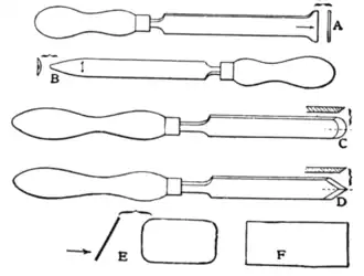
Fig. 21.—Group of Scrapes.
A, Metal-worker's scrape, pushed straightforward.
B, Ditto, operated laterally.
C, Round-nosed tool used by wood-turners.
D, Diamond point used by wood-turners.
E, F, Cabinet-makers' scrapes.
chief advantage of backing-off or relieving is in its application to cutters of intricate curves, which would be difficult or impossible to sharpen along their edges. Such cutters, moreover, if made with
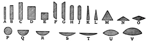
Fig. 22.—Cross-sectional Shapes of Files.
A, Warding.
B, Mill.
C, Flat.
D, Pillar.
E, Square.
F, G, Swaged reapers.
H, Mill.
J, Topping.
K, Reaper.
L, Knife.
M, Three-square.
N, Cant.
O, Slitting or feather-edge.
P, Round.
Q, Pit-saw or frame-saw.
R, Half-round.
S, T, Cabinet.
U, Tumbler.
V, Crossing.
ordinary teeth would soon be worn down, and be much weaker than the strong form of teeth represented in fig. 20. The relieving is usually done in special lathes, employing a profile tool which cuts the surface

Fig. 23.—Longitudinal Shapes of Files.
A, Parallel or blunt.
B, Taper bellied.
C, Knife reaper.
D, Tapered square.
E, Parallel round.
F, Tapered triangular.
G, Parallel round.
H, Taper or rat-tail.
J Parallel half-round.
K, Tapered half-round.
L, Riffler.