Page:EB1911 - Volume 25.djvu/1039
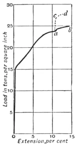
is found only after a considerable addition has been made to the load. The result is, as in the former case, to give greater ultimate strength and less ultimate elongation. Fig. 14 exhibits two experiments of this kind, made with annealed iron wire. A
 |
|
| Fig. 13. | Fig. 14. |
load of 23½ tons per square inch was reached in both cases; ab shows the result of continuing to load after an interval of five minutes, and acd after an interval of 45½ hours, the stress of 23½ tons being maintained during the interval in both cases.[1]
It may be concluded that, when a piece of metal has in any way been overstrained by stress exceeding its limits of elasticity, it is hardened, and (in some cases at least) its physical properties go on slowly changing for days or even months. Instances of the hardening effect of permanent set occur when plates or bars are rolled cold, hammered cold, or bent cold, or when wire is drawn. When a hole is punched in a plate the material contiguous to the hole is severely distorted by shear, and is so much hardened in consequence that when a strip containing the punched hole is broken by tensile stress the hardened portion, being unable to extend so much as the rest, receives an undue proportion of the stress, and the strip breaks with a smaller load than it would have -borne had the stress been uniformly distributed. This bad effect of punching is especially noticeable in thick plates of mild steel. It disappears when a narrow ring of material surrounding the hole is removed by means of a rimer, so that the material that is left is homogeneous. Another remarkable instance of the same kind of action is seen when a mild-steel plate which is to be tested by bending has a piece cut from its edge by a shearing machine. The result of the shear is that the metal close to the edge is hardened, and, when the plate is bent, this part, being unable to stretch like the rest, starts a crack or tear which quickly spreads across the plate on account of the fact that in the metal at the end of the crack there is an enormously high local intensity of stress. By the simple expedient of planing off the hardened edge before bending the plate homogeneity is restored, and the plate will then bend without damage.
Annealing.—The hardening effect of overstrain is removed by the process of annealing, that is, by heating to redness and cooling slowly. In the ordinary process of rolling plates or bars of iron or mild steel the metal leaves the rolls at so high a temperature that it is virtually annealed, or pretty nearly so. The case is different with plates and bars that are rolled cold: they, like wire supplied in the hard-drawn state (that is, without being annealed after it leaves the draw-plate), exhibit the higher strength and greatly reduced plasticity which result from permanent set.
Extensometers.—Much attention has been paid to the design of extensometers, or apparatus for observing the small deformation which a test-piece in tension or compression undergoes before its limit of elasticity is reached. Such observations afford the most direct means of measuring the modulus of longitudinal elasticity of the material, and they serve also to determine the limits within which the material is elastic. In such a material as wrought iron the elastic extension is only about 1/12000 of the length for each ton per square inch of load, and the whole amount up to the elastic limit is perhaps 1/1000 of the length; with a length of 8 in., which is usual in tensile tests, it is desirable to read the extension to, say, 1/50000 in. if the modulus of elasticity is to be found with fair accuracy, or if the limits of proportionality between strain to stress are under examination. Measurements taken between marks on one side of the bar only are liable to be affected by bending of the piece, and it is essential either to make independent measurements on both sides or to measure the displacement between two pieces which are attached to the bar in such a manner as to share equally the strain on both sides.
In experiments carried out by Bauschinger, independent measurements of the strains on both sides of the bar were made by using mirror micrometers ot the type illustrated diagrammatically in fig. 15. Two clips a and b clasp the test-piece at the place between

Fig. 15.
which the extension is to be measured. The clip b carries two small rollers d1 d2 which are free to rotate on centres fixed in the clip. These rollers press on two plane strips c1 c2 attached to the other clip. When the specimen is stretched the rollers consequently turn through angles proportional to the strain, and the amount of turning is read by means of small mirrors g1 and g2, fixed to the rollers, which reflect the divisions of a fixed scale f into the reading telescopes e1 e2 . In Martens's extensometer each of the rollers is replaced by a rhombic piece of steel with sharp edges, one of which bears against the test-piece, while the other rests in a groove formed in the spring projecting parallel to the test-piece from the distant clip. Much
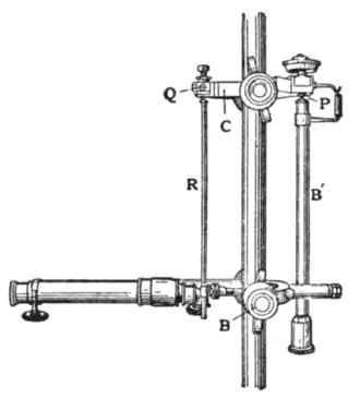
Fig. 16.
excellent work has been done by extensometers of this class, but in point of convenience of manipulation it is of great advantage to have the apparatus self-contained. J. A. Ewing has introduced a microscope extensometer of the self-contained type which is shown in fig. 16; its action will be seen by reference to the diagram fig. 17. Two clips B and C are secured on the bar, each by means of a pair of opposed set-screws. Between the two is a rod B′ which is hinged to B and has a blunt pointed upper end which makes a ball-and-socket joint with C at P. Another bar R hangs from C, and carries a mark which is read by a microscope attached to B. Hence, when the specimen stretches, the length of B′ being fixed, the bar R is pulled up relatively to the microscope, and the amount of the movement
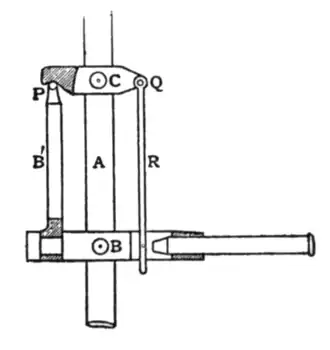
Fig. 17.
is measured by a micrometer scale in the eyepiece. A screw at P serves to bring the mark on R into
- ↑ J. A. Ewing, Proc. Roy. Soc. (June, 1880).