Page:EB1911 - Volume 24.djvu/1022
been verified in a few cases, the value adopted for E, being that for a riveted structure or about 10,000 tons per square inch. In some model experiments made in air and in water, the frequency in the latter case was found to be reduced, and owing to the rapid damping of the free vibrations and to a virtual increase in the mass-inertia caused by the concomitant motion of the surrounding water, which occurs in the ship and not in the model when vibrated in air, there must be a difference in the results. A second difference is due to the ratio of depth to length in a ship being sufficient to make the term for rotational inertia appreciable, which factor is neglected in the formulae for a thin bar and the dynamic model. The extent to which such results require modification cannot, be determined until further experiments have been made.
Finally it appears that vibration in a ship can generally be avoided only by removing its cause; the addition of further stiffening to the structure with the object of reducing vibration has not infrequently had the opposite effect, the natural frequency being brought more nearly into synchronism with that of the disturbing force.
The adoption of the steam turbine obviates many of the causes producing vibration referred to above, leaving only those due to the forces resulting from inequalities in the working or position of the propellers.
Steering.
The information available on the steering and manoeuvring qualities of ships is largely due to the results of the methodic trials made with H.M. ships. These include observations of the paths when turning under different angles of helm, at various speeds, with and without assistance from the propellers, and with variation in certain features of the hull which influence the steering, such as the addition of bilge keels, change of draught or trim, and the omission of the after deadwood.
One of the first attempts at plotting the curve traversed by a ship under the action of her rudder, and the position of the ship at any instant with reference to that curve, was made by the writer in 1877 with H.M.S. “Thunderer” (see Appendix XIII. to Report of “Inflexible’s” Committee).[1] The position of the ship was fixed at numerous intervals with reference to the line of advance by observing simultaneously (a) the direction of her head and (b) the angles of the base of a triangle, whose apex was a floating object within the approximate circle in which she turned, and whose base was the line between two observers at fixed points on the deck, one forward and the other aft; these angles in conjunction with the base fixing the distance of the middle line plane of the ship from the floating object. The data were observed for different speeds and with different angles of rudder, and with and without the turning effect of the screws.
Fig. 61 gives the plotted positions of the ship continued for two complete turns with 31° of helm when going ahead initially at 10·5 knots. The straight line which becomes curved at the point A is the initial course of the ship. The short lines give the positions of the ship when turning at intervals of a minute; and the curve drawn touches the positions successively occupied by the middle line of the ship. It will be seen that the bow of the ship is nearer the centre of the circle, or curve in which she turns, than the stern. The vessel may be regarded as going ahead and turning or pivoting about a point well forward in her middle line; this is termed the “pivoting point,” the middle line being, at this point, a tangent to the curve concentric with and similar to that described by her centre of gravity. In the “Thunderer” the pivoting point was situated about 50 ft. abaft the stem.
Similar information for a more modern ship is given in fig. 62 for the Japanese battleship “Yashima” when turning under 32° of helm with an initial speed of 17·5 knots.[2] AAA is, the locus of the pivoting point O, and BBB that of the ship’s centre of gravity. The bow of the ship is directed inwards with reference to the latter curve; the angle between the middle line plane and the tangent to the curve BBB is termed the “drift angle.”
The distance between the pivoting point and the ship’s centre of gravity is equal to ρ sin φ, where ρ is radius of curvature of BBB and φ is the drift angle. The value of φ is about 23° in the “Yashima,” and about 10° in the “Thunderer”; and the pivoting point O of the former ship is situated very near the fore end of the vessel. CCC is the path of the outer edge of the stern and represents the clear space required when turning.
In both ships the path is spiral in form until about 16 points (180°) have been turned through, and it then becomes approximately a circle. The maximum distance that the ship’s centre of gravity travels in her original direction after the helm is put over is termed the “advance,” and the “tactical diameter” is the Perpendicular distance between the original line of advance and the ship’s position after turning through 16 points.
For an approximate investigation of the forces in operation during the turning of a ship, the, motion may be divided into three stages: (a) when the rudder is first put over and the pressures on the hull are those necessary to produce angular acceleration; (b) when the accelerative forces are combined with those caused by the resistance of the ship to rotation; and Nature of forces when turning. (c) when finally turning uniformly in a circular path. The characters of the forces acting during the states (a) and (c) can be ascertained, and the type of motion under the complex conditions represented by (b) will consist of a gradual replacement of the motion at (a) by, that at (c).
Initially, on putting the helm over, the change in the stream line motion at the stern produces a pressure upon the rudder normal to its plane. If the rudder is unbalanced, there is generally an additional pressure upon the after deadwood caused by the widening of the stream lines approaching the rudder. The resultant of these pressures on rudder and deadwood is a force P at the stern which may be resolved longitudinally and transversely into R and Q, where R tends to reduce the speed of the ship and Q to move the stern outwards (fig. 63).
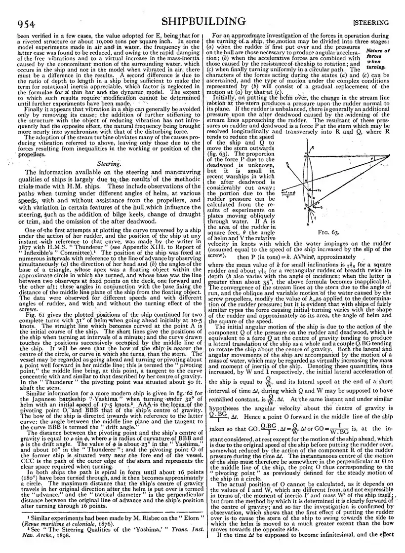
Fig. 63.
The proportion of the force P due to the deadwood is unknown, but it is small in recent warships in which the after deadwood is considerably cut away; the portion due to the rudder pressure can be calculated from the results of experiments on plates moving obliquely through water. If A is the area of the rudder in square feet, θ the angle of helm and V the relative velocity in knots with which the water impinges on the rudder (assumed equal to the speed of the ship increased by the slip of the screw),
then P (in tons)=k. AV2sinθ, approximately
where the mean value of k for small inclinations is 1/270 for a square rudder and about 1/370 for a rectangular rudder, of breadth twice its depth (k also varies with the angle of incidence; when the latter is greater than about 35°, the above formula becomes inapplicable). The convergence of the stream lines at the stern due to the angle of run, and the oblique and variable motion of the water caused by the screw propellers, modify the value of k, as applied to the determination of the rudder pressure; but it is evident that with ships of fairly similar types the force causing initial turning varies with the shape of the rudder and approximately as its area, the angle of helm and the square of the speed.
The initial angular motion of the ship is due to the action of the component Q of the pressure on the rudder and deadwood, which is equivalent to a force Q at the centre of gravity tending to produce a lateral translation of the ship as a whole and a couple Q.BG tending to rotate the ship about the centre of gravity. Both the lateral and angular movements of the ship are accompanied by the motion of a mass of water, which may be regarded as virtually increasing the mass and moment of inertia of the ship. Denoting these quantities, thus increased, by W and I respectively, the initial lateral acceleration of the ship is equal to Q/W, and its lateral speed at the end of a§ short interval of time Δt, during which Q and W may be supposed to have remained constant, is Q/W.Δt. At the same instant and under similar hypotheses the angular velocity about the centre of gravity is Q.BG/I.Δt. Hence a point O forward in the middle line of the ship taken so that GO.Q.BG/I.Δt=Q/W.Δt or GO=I/W.BG is, at the instant considered, at rest except for the motion of the ship ahead, which is due to the original speed of the ship before putting the rudder over, somewhat reduced by the action of the component R of the rudder pressure during the time Δt. The instantaneous centre of the motion of the ship must therefore be somewhere in the perpendicular at O to the middle line of the ship, the point O thus corresponding to the “pivoting point” as previously defined for the steady motion of the ship in a circle.
The actual position of O cannot be calculated, as it depends on the values of I and W, which are different from, and not expressible in terms of, the moment of inertia I′ and mass W′ of the ship itself; but from the method by which it is determined it is clearly forward of the centre of gravity; and so far the investigation is confirmed by observation, which shows that the first effect of putting the rudder over is to cause the stern of the ship to swing towards the side to which the helm is moved to a much greater extent than the bow moves towards the opposite side.
If the time Δt be supposed to become infinitesimal, and the effect